Using a Digital Multimeter
moboclassified November 4, 2026 No Comments
What is a digital multi-meter?
A digital multi-meter is a test tool used to measure basic electrical values namely voltage, current, capacitance and resistance. It is also used to test for continuity in a conductor.
Parts and functions of a Digital multi-meter
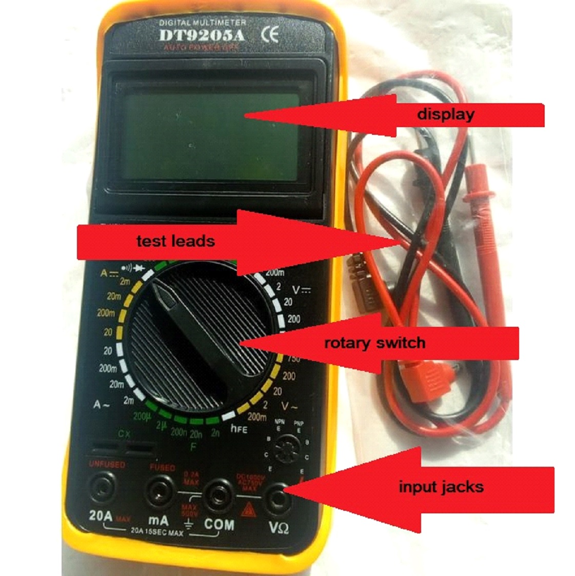
Display: This is the where measurement values or readouts can be seen
Test leads: These are flexible insulated wires which are to be inserted into the input jacks.
Rotary switch: This is meant for selecting measurement values e.g voltage, current or resistance.
Input jacks: These are points where the test leads are being inserted
For the purpose of this training, a DMM single 32 position switch for function and range with model number DT-9205A is used. It is very common in the Nigerian market.
What Values can be measured with a digital multi-meter(DMM)?
Voltage: Voltage is the pressure from an electrical circuit’s power source that pushes current through a conducting loop, enabling them to do work such powering an electric bulb. The symbol for voltage is V.
Current: Current is the rate of flow of electric charge through a conductor. Current is measured in Ampere(A).
Resistance: Resistance is a measure of the opposition to current flow in an electrical circuit. It is measured in ohms(Ω)
Capacitance: Capacitance is the ability of a component or circuit to collect and store electrical charge. It is measured in Farad(F)
Contuinity: Testing for continuity is required to ascertain the presence of a complete path for current flow.
How and where do you insert your test leads in your multi-meter?
Most DMM carry four input jacks.
In the course of this training, the DMM we are using carry four input jacks.
Kindly note that the black test lead is for negative while the red test lead is for positive.
⦁ The black test lead(negative) is meant to be inserted into the COM(common) input jack.
⦁ To test or get values for Voltage or Resistance, you would insert the red test lead(positive) in the input jack labelled V & Ω.
⦁ To test or get values for current; there is a special connection for current measurements, and sometimes a separate one for either low or high current measurements.
The input jack labelled mA(milliampere) is used to test for low current(0.2 A max).
Kindly note that 1 milliampere [mA] = 0.001 ampere [A]
While the second input jack is used to test for high currents(20 A max)
Select the correct one for the current measurement to be made. It is advisable to always select the input jack with 20A max label to prevent blowing up the fuse of the meter
How do I know How to set the rotary switch to take correct readings?
The rotary switch is divided into six sections namely DC voltage, AC voltage, DC current, AC current, capacitance and resistance.
The DMM we are using during the course of this training is illustrates these various sections with different colors namely green white and yellow.
⦁ DC voltage(V⎓) is labelled white
⦁ AC voltage(V ∿) is labelled yellow
⦁ DC current(A⎓) is labelled yellow
⦁ AC current(A ∿) is labelled white
⦁ Capacitance(F) is labelled green
⦁ Resistance(Ω) is labelled green
It is very important to know how to set the rotary switch correctly.
If you set it incorrectly, you might blow out the fuse of your DMM. This means that you will need to service your DMM before it can used to take readings again.
What is AC and DC?
Electricity flows in two ways: It can flow either in an alternating current (AC) or in a direct current (DC).
Electricity or “current” is the movement of electrons through a conductor, like a wire.
The difference between AC and DC lies in the direction in which the electrons flow.
In DC, the electrons flow steadily in a single direction, or “forward.” In AC, electrons keep switching directions, sometimes going “forward” and then going “backward.”
Direct current can be obtained from a cell or battery. The symbol for direct current is ⎓
If you look closely at your DMM, you would find that symbol on it.
You would find something like V⎓ and A⎓
Remember we discussed earlier that V stands for voltage and A stands for current
So if you want to measure DC voltage across a component or battery:
⦁ Ensure that the black test lead which is your negative is inserted into the COM(common) input jack
⦁ Ensure that the red test lead which is your positive is inserted into the input jack labelled V & Ω.
⦁ Set your rotary switch on a value that is far higher than the assumed voltage of the battery. If you are testing a 12 volts battery, you can set your rotary switch on the value of 20. If you set it on a value below 12, it can cut the fuse of your DMM which would require servicing to work again.
⦁ Place the black test lead on the negative terminal of your battery and the red test lead on the positive terminal
The DMM display will project the voltage across the circuit.
If you want to measure the DC current flowing across a circuit:
Remember that current is the strength of electricity flowing through a circuit
⦁ Ensure that the black test lead which is your negative is inserted into the COM(common) input jack
⦁ Ensure that the red test lead which is your positive is inserted into the input jack labelled 20A. We selected 20A max because we assume that we cannot say for sure how much current is flowing within the component.
⦁ Set your rotary switch on the value labelled 20 in the A⎓ DC current section which is the maximum your DMM can read.
⦁ Electric current flows from positive to negative. So you would place your red test lead at the most positive side(source) of the circuit while the black test lead will be placed on the negative side of the circuit. It is conventional that current moves from the source(positive side) to the negative side).
The display will project the current flowing though the circuit
AC current ∿ is supplied from a mains or electric generator
If you want to measure AC current
Remember that current is the strength of electricity flowing through a circuit
⦁ Ensure that the black test lead which is your negative is inserted into the COM(common) input jack
⦁ Ensure that the red test lead which is your positive is inserted into the input jack labelled 20A. We selected 20A max because we assume that we cannot say for sure how much current is flowing within the component.
⦁ Set your rotary switch on the value labelled 20 in the A ∿ AC current section which is the maximum your DMM can read.
⦁ Electric current flows from positive to negative and vice versa consistently in the AC circuit. So you would place your test leads at selected ends of the circuit.
The display will project the current flowing through the circuit.
If you want to measure AC voltage
⦁ Ensure that the black test lead which is your negative is inserted into the COM(common) input jack
⦁ Ensure that the red test lead which is your positive is inserted into the input jack labelled V & Ω.
⦁ Set your rotary switch on a value that is far higher than the assumed voltage through the component. If the assumed voltage is 220, you can set your rotary switch on the value of 750. If you set it on a value below 200, it can cut the fuse of your DMM which would require servicing to work again.
⦁ Place the black test lead on one end and the red test lead on the other.
The voltage or unit of electrical potential will be displayed
How to test for continuity
⦁ Ensure that the black test lead which is your negative is inserted into the COM(common) input jack
⦁ Ensure that the red test lead which is your positive is inserted into the input jack labelled V & Ω.
⦁ Set your rotary switch on a value that displays ( ).
⦁ If you use the two test leads to touch one another, your DMM should make a beeping noise continuously until you separate the test leads.
So if you touch a conductor with your test leads one end against another, if it is broken, your DMM won’t make any noise.
If the conductor has a complete path for current flow, it would make a beeping sound.
Leave a Comment
Your email address will not be published. Required fields are marked. *